4STB-E Trans-Brake Overdrive Lock/Up (w/Foot-Brk Disable)
OPERATING INSTRUCTIONS AND WIRING
For use with Auto Reset Relay Controller #10
(White Plug Connector)
Your high performance transmission is now equipped with the finest and safest full manual valvebody available today. It comes standard with the electrically activated Overdrive and Lock-Up features. It may also include our optional internal Trans-brake feature. The following information covers both the wiring and operation of all these features in order to make your use of the 4STB-E (AODE/4R70W) transmission both rewarding and enjoyable.
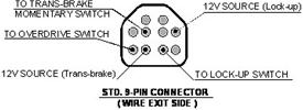
WIRING and Operation (9-pin) Feb (2012)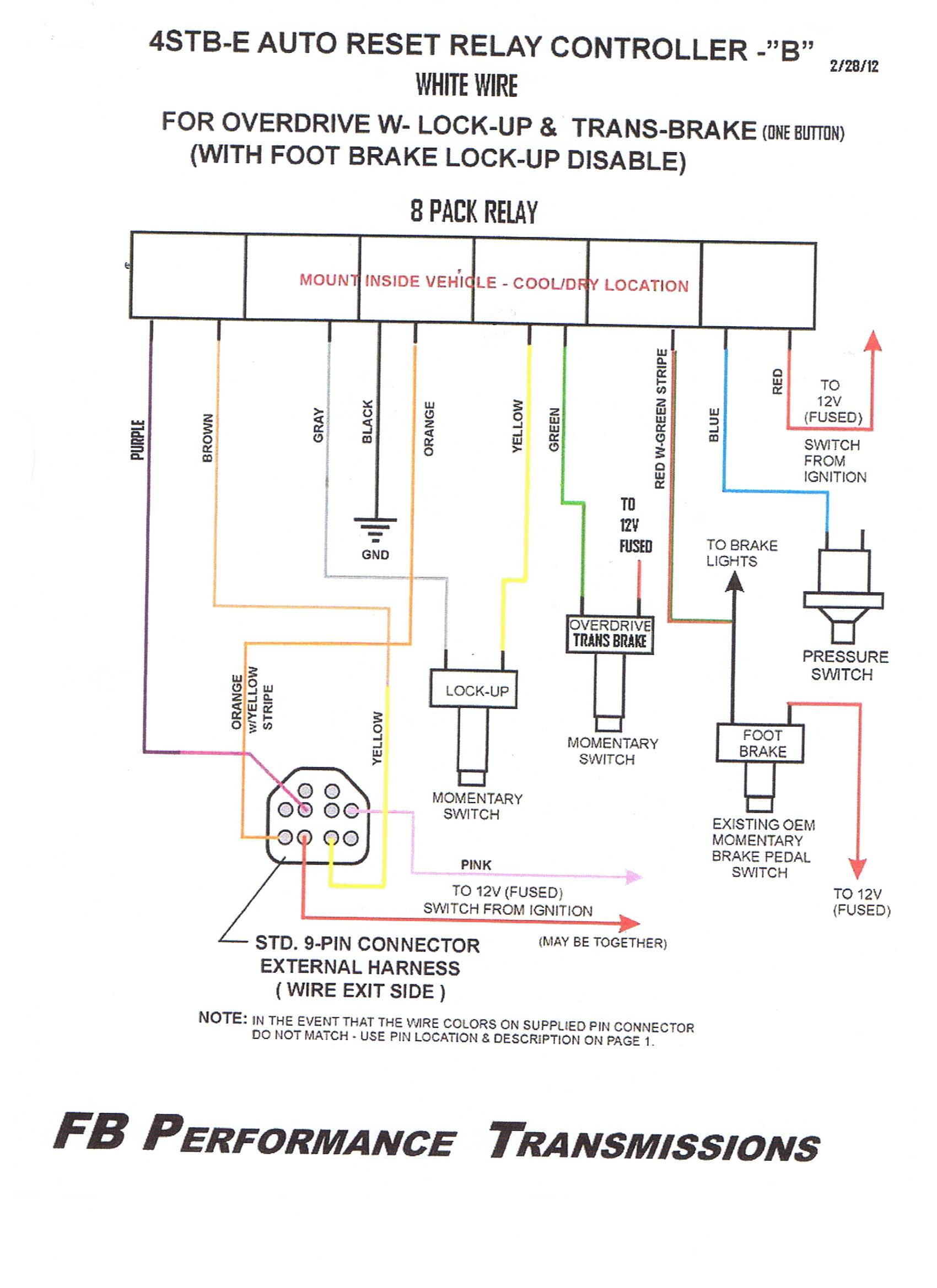
Wiring connections are required to make all of the electrical features functional. This connection is provided with a pig-tail with (5) colored wires. Each wire must be connected properly as described:
1. Yellow wire (Lock-up) connected to the brown wire on Relay Controller.
Used to activate and deactivate the converter Lock-up feature in Over-drive or 3rd Gear.
The Lock-up feature will automatically deactivate when either circumstance occurs:
a) When the shifter lever is moved out of the 3rd gear position (toward Neutral or 2nd Gear).
b) When the brake pedal is depressed.
Lock-up will automatically deactivate when the shifter lever is moved out of the 3rd gear position.
Note: If optional 3rd-gear lock-up is included, the Lock-up feature must be wired independently.
2. Orange w/Yellow Stripe wire (Over-drive) - connected to the orange wire on Relay Controller. This is used to activate and deactivate the transmission's Over-drive feature. This can only be activated when the transmission is in 3rd gear. Overdrive will automatically deactivate when the shifter lever is moved out of the 3rd gear position. Over-drive is strictly a cruising gear.
You cannot activate Over-drive under full throttle conditions. Doing so will damage the transmission.
Note: If optional 3rd-gear lock-up is included, the Lock-up feature must be wired separately.
3. Pink wire (Lock-up) - connected to a reliable (fused) ignition 12 volt power source. This will provide continuous power to the Lock-up function when the ignition is on.
4. Pink w/Black Stripe wire (Trans-brake) - connected to a reliable (fused) ignition 12 volt power source. This will provide continuous power for the Tran-brake function when the ignition is on. (An optional toggle switch can also be used to switch power and disable the Trans-brake solenoid entirely).
5. Purple wire (Trans-brake) - connected to "momentary" switch (similar to a Line-lock switch) that is also connected to a good ground source. The momentary switch should be mounted in a convenient location in the cockpit (like the shifter or steering wheel) to activate the Trans-brake.
Note: Please check the actual wire colors on the pig-tail connector you received. If they are different from those specified above use only the 9-Pin Connector diagram (Top of the page) to determine the wire and functional hook-ups. The transmission functions and their locations on the connector will not change.
Optional: We have found that by hooking up the Trans-brake in conjunction with a roll-control system allows the car to be staged perfectly at any desired rpm. If your car is not equiped with a roll system type a micro-switch will do a similar job just as well
SPECIAL NOTES: The transmission shift pattern is P-R-N-(E/OD)3-2-1 *Remember the Trans-brake must not be engaged while the vehicle is in motion!!
Do not hit the trans-brake while in 1st gear and the car is moving.
Once the transmission has been shifted into 3rd, the toggle switch (or whatever switch you're using), can be closed causing the transmission to shift into over-drive (4th). It will stay in overdrive until the switch is opened. It is highly recommended that you open the switch before you come to a stop. If the switch is left closed (Overdrive On), the transmission will shift directly into overdrive when the shift lever is moved from 2nd to 3rd gear when up-shifting. This is not recommended and transmission durability will be compromised.
OPERATION Trans-brake:
1. The transmission has a 3- speed Forward Shift Pattern. The Trans-brake will apply only in low (1st) gear. Reverse is engaged by shifting into reverse and then applying the Trans-brake button. This is a built-in safety feature.
2. Stage the car with the engine above 1000 RPM to obtain higher fluid pressure and volume which will provide a quicker trans-brake engagement.
3. Maximum engine rpm with the trans-brake applied, creates excessive heat very quickly. (40 to 50 degrees/sec) On a full tree, wait for the next to the last yellow bulb, before bringing the engine speed to the full stall rpm. Always use an adequate trans fluid cooler (min. 25,000 GVW capacity) and inspect the condition of the trans fluid very often.
4. For proper operation, the trans-brake solenoid should only be used with a fully charged 12 volt battery source in order for it to function properly.
5. If any operational problems occur with the trans-brake, check the activation button, all electrical connections, and the by-pass delay box if one is used.
6. If you should encounter a delay or hesitation in the release of the trans-brake, check the following:
a. The fluid level in the transmission; a low level can cause a delay in trans-brake release.
b. A faulty release switch; check operation of the switch used to release the trans-brake.
7. Since the trans-brake only works in 1st gear, if you should accidentally hit the activating switch while in any other gear, the mechanism will not engage. This is a built in safety feature.
8. The transmission will operate normally, even if you choose not to use the trans-brake. Simply flip the toggle switch to the off position. The trans-brake itself is an "added" feature for your transmission and cannot adversely affect the transmission's operation when it is not being used.
Reaction Time is influenced by the following:
1. Position the driver stages the car in relation to the racetrack timing lights.
2. The type of trans-brake button that is used, its location, and when the driver releases it.
3. Release speed of the trans-brake.
4. Weight of the racecar.
5. Horsepower of the engine and the rpm when it produces peak torque.
6. Stall speed and torque multiplication characteristics of the torque converter.
7. Gear ratio's of the transmission and rear axle.
8. Type of chassis and suspension, how it is set up and adjusted.
9. Diameter of the front tires.
10. Drag slick size, the sidewall construction, rubber compound, age or condition, inflation
pressure, and the width of the rims they are mounted on.
11. Type and positioning of the race track timing lights (their height and distance apart).
NOTE: Racecars that produce quick reactions times on a "pro" start tree, are generally setup to lift the front tires out of the timing lights. This method works great on most cars, but will cause a consistency problem on some cars. Consistent reaction times require positioning the race car the same distance into the staging light beam every time.
4STB-E AUTO RESET
RELAY CONTROLLER- WIRING
OVERDRIVE and LOCK-UP
WIRE COLOR FUNCTION
- BLUE.............Oil Pressure switch on side of trans. (either terminal doesntt matter)
- RED..............12v+ switched from ignition (fused)
- BLACK............Ground
- YELLOW.........to L/U button
- GRAY.............to L/U (YELLOW and GRAY are NOT polarity sensitive!!!)
- WHITE...........to O/D button
- GREEN...........to O/D button (WHITE and GREEN are NOT polarity sensitive)
- ORANGE.........to O/D solenoid wire from trans. (usually orange with yellow stripe wire coming out of 9 pin connector)
- BROWN..........to L/U solenoid wire from trans. (usually yellow wire coming out of 9 pin connector)
NOTE: Transmission case must be properly grounded for this system to operate correctly. O/D and L/U switches can be any 2 prong single throw momentary switch. Regular on/off toggle switch will not work with this system. These instructions are for Rostra wire harness only!