Technical Advice 2004

Latest

Posted On: November 08, 2018
Posted On: November 07, 2018
Posted On: April 13, 2016

Subscribe

Via Email:

High Stall Torque Converters

Posted On: April 30, 2004

High stall torque converters are very desirable in drag race vehicles because they allow the engine to develop maximum torque (say 5000 rpm), before the vehicle leaves the starting line.  This type of converter is designed to slip more, or have a higher stall speed then the typical 1300-1900 rpm factory converter.  Modifying an engine for increased power will raise the rpm it produces at this new usable horsepower.  When the engine power is increased, it will require matching the proper high-stall torque converter.  This is important, in order to allow the engine to reach its usable horsepower range before the converter reaches its stall speed, and hydraulically loads the engine.   Stall speed is the maximum rpm that an engine can obtain against the hydraulic load of the torque converter with the transmission shaft held stationary.

The best performance is obtained with a converter that has a stall speed slightly higher than the rpm of the engine when it starts to produce its strongest usable power.  Too low of a stall speed will result in a bog, and launches will be slow, since the engine will not be in it's usable power range.  Too high of a stall speed will result in the engine reaching its peak power range below the rpm.  Since the converter can efficiently transfer power, this could result in excessive slippage.

The stall speed is controlled by the converter, engine power, and the ability to hold the transmission input shaft stationary.  When engine power is increased, stall speed will go up.  Likewise, when engine power is decreased, stall speed will go down.  Stall speeds with this type of torque converter are generally rated as what's termed the "Flash Stall Speed" or shock. This is the approximate rpm that the engine will go to when the throttle is quickly moved from the idle position to the wide open throttle with the transmission engaged.

This "Flash Stall Speed" will vary depending upon engine power, rear end ratio, and car weight.  It is very important to match all of the engine components; cam, carburetor, torque converter, rear end gear ratio, etc, to work in the same rpm range for the best results.  When modifying the engine, do not over cam or over carburete the engine.  These are two of the most common mistakes.

Select a rear-end gear ratio that will allow the modified engine and the high stall torque converter to perform efficiently in the rpm range they were built for.  A general recommendation, would be to use gears in the following ranges:

3.10 to 3.50 for 2,400 to 2,800 rpm stall converter,

3.50 to 4.10 for 3,000 to 3,800 rpm stall converter,

4.10 and higher range with higher stall converters.

Keep in mind, for a given stall speed, the turbine shaft is held stationary with either the wheel brakes or the transmission brake until the driver is ready to take off.  The use of a trans-brake allows the driver to make maximum use of a given stall speed.  Stall speed will be limited in cars without a transmission brake.  This is because the gear reduction of the transmission and the rear end would provide enough mechanical advantage to overcome the car's wheel brake system.  When using the wheel brakes, often the best launch technique for a high stall converter is to leave from a fast idle.  This will allow the converter to momentarily flash to a higher stall speed (Flash Stall Speed).  This is better then bringing the engine rpm up against the converter and car brakes and also preloading the suspension.   When using this launch technique, the engine must idle clean and have a stumble free response to throttle movement.

0

The Transmission Brake

Posted On: April 29, 2004

A transmission brake is usually considered a drag racing "only" automotive after-market device. It operates by simultaneously applying the forward and reverse clutch packs of an automatic transmission while its both in gear, and the torque converter is at or near it's stall speed. At the moment the trans-brake is disengaged the reverse element is released (usually the engine is revving at peak power) and the car will immediately lunge forward from its starting position.

You might wonder what the difference is between holding back a revving car in gear with just the wheel brakes versus that with a trans-brake. In order to understand this difference, more must be explained about the car's suspension, and how it operates during the initial take-off. 

If your car has a rear-axle drive with a solid suspension, it most likely also has what's called "anti-squat". This term defines the function of the rear suspension geometry that prevents the body of the car from "squatting" during it's initial acceleration. In fact, the rear of the car will rise if the anti-squat factor is high enough to overcome the inertial forces encountered during this initial acceleration. Many cars from Detroit incorporate an anti-squat design in order to prevent suspension "bottoming" during initial acceleration. You can find out if your car has this feature by performing a simple stall test and if the rear end rises, it has anti-squat. If your car has an independent rear suspension, such as the Corvette, it will squat because this type suspension has a "pro-squat" type geometry built into it.

How is the trans-brake and the rear suspension related? Keep in mind that for every force in one direction, there is an equal and opposite force in another. The force that is opposite to the raising of the rear will appear as high instant tire loading during initial acceleration. Its instantaneous because this force only occurs at a moment during the initial launch. This at the time between when the car is at rest and when full power is being transferred to the rear suspension.

Since the traction forces of the rear tires usually increase relative to their contact patch force, a car having more anti-squat will always have a higher acceleration and therefore will launch much quicker. If the wheel brakes are used for staging, the rear suspension becomes preloaded and all the anti-squat factor is already used up. When a trans-brake is used for staging, the rear suspension remains at rest and is unloaded. At the moment you flick the switch and release the trans-brake, the immediate transfer of engine torque "shocks" or loads the rear suspension, performing as it would with a stick-shift car. The trans-brake also prevents the high-powered/high stall car from overpowering its brakes on the line. By comparison, the trans-brake release action is much faster than lifting your foot off the brake pedal (or even a clutch pedal for that matter).

The trans-brake is used in conjunction with a specially calibrated full manual valve body. During operation the transmission will function normally, even if you choose not to use the trans-brake. A toggle switch is used to simply turn off its operation. Since the trans-brake is an added feature, the operation of the transmission can not be adversely affected when it is not being used.

The FB trans-brake is available for the following types of high performance transmissions:

GM - TH350 /TH400 / Powerglide

FORD - C-4 / C-6 / 4STB / AO3

MOPAR - TF727 

0

Special Instructions for the 4STB-E Transmission

Posted On: February 29, 2004

4STB-E  Trans-Brake Overdrive Lock/Up (w/Foot-Brk Disable)

OPERATING INSTRUCTIONS AND WIRING

For use with Auto Reset Relay Controller #10

(White Plug Connector)
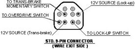
  

 Your high performance transmission is now equipped with the finest and safest full manual valvebody available today.  It comes standard with the electrically activated Overdrive and Lock-Up features.  It may also include our optional internal Trans-brake feature. The following information covers both the wiring and operation of all these features in order to make your use of the 4STB-E (AODE/4R70W) transmission both rewarding and enjoyable.

WIRING and Operation (9-pin)  Feb (2012)
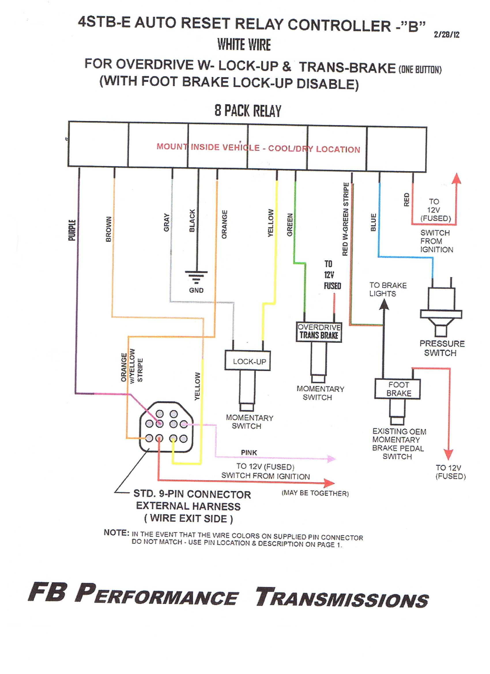
Wiring connections are required to make all of the electrical features functional.  This connection is provided with a pig-tail with (5) colored wires.  Each wire must be connected properly as described:

1. Yellow wire (Lock-up) connected to the brown wire on Relay Controller. 

Used to activate and deactivate the converter Lock-up feature in Over-drive or 3rd Gear.

The Lock-up feature will automatically deactivate when either circumstance occurs:

a)    When the shifter lever is moved out of the 3rd gear position (toward Neutral or 2nd Gear).

b)    When the brake pedal is depressed.

Lock-up will automatically deactivate when the shifter lever is moved out of the 3rd gear position.

Note: If optional 3rd-gear lock-up is included, the Lock-up feature must be wired independently.

2. Orange w/Yellow Stripe wire (Over-drive) - connected to the orange wire on Relay Controller.  This is used to activate and deactivate the transmission's Over-drive feature.  This can only be activated when the transmission is in 3rd gear.  Overdrive will automatically deactivate when the shifter lever is moved out of the 3rd gear position.  Over-drive is strictly a cruising gear.

You cannot activate Over-drive under full throttle conditions.  Doing so will damage the transmission.

Note: If optional 3rd-gear lock-up is included, the Lock-up feature must be wired separately.

3. Pink wire (Lock-up) - connected to a reliable (fused) ignition 12 volt power source.  This will provide continuous power to the Lock-up function when the ignition is on.

4. Pink w/Black Stripe wire (Trans-brake) - connected to a reliable (fused) ignition 12 volt power source.  This will provide continuous power for the Tran-brake function when the ignition is on.  (An optional toggle switch can also be used to switch power and disable the Trans-brake solenoid entirely).

5. Purple wire (Trans-brake) - connected to "momentary" switch (similar to a Line-lock switch) that is also connected to a good ground source.  The momentary switch should be mounted in a convenient location in the cockpit (like the shifter or steering wheel) to activate the Trans-brake.

Note: Please check the actual wire colors on the pig-tail connector you received.  If they are different from those specified above use only the 9-Pin Connector diagram (Top of the page) to determine the wire and functional hook-ups.  The transmission functions and their locations on the connector will not change.

Optional: We have found that by hooking up the Trans-brake in conjunction with a roll-control system allows the car to be staged perfectly at any desired rpm.  If your car is not equiped with a roll system type a micro-switch will do a similar job just as well

SPECIAL NOTES: The transmission shift pattern is P-R-N-(E/OD)3-2-1 *Remember the Trans-brake must not be engaged while the vehicle is in motion!!

Do not hit the trans-brake while in 1st gear and the car is moving.

Once the transmission has been shifted into 3rd, the toggle switch (or whatever switch you're using), can be closed causing the transmission to shift into over-drive (4th).  It will stay in overdrive until the switch is opened.  It is highly recommended that you open the switch before you come to a stop.  If the switch is left closed (Overdrive On), the transmission will shift directly into overdrive when the shift lever is moved from 2nd to 3rd gear when up-shifting.  This is not recommended and transmission durability will be compromised.

OPERATION Trans-brake:

1. The transmission has a 3- speed Forward Shift Pattern.  The Trans-brake will apply only in low (1st) gear.   Reverse is engaged by shifting into reverse and then applying the Trans-brake button. This is a built-in safety feature.

2. Stage the car with the engine above 1000 RPM to obtain higher fluid pressure and volume which will provide a quicker trans-brake engagement.

3. Maximum engine rpm with the trans-brake applied, creates excessive heat very quickly.  (40 to 50 degrees/sec)  On a full tree, wait for the next to the last yellow bulb, before bringing the engine speed to the full stall rpm.  Always use an adequate trans fluid cooler (min. 25,000 GVW capacity) and inspect the condition of the trans fluid very often. 

4. For proper operation, the trans-brake solenoid should only be used with a fully charged 12 volt battery source in order for it to function properly.

5. If any operational problems occur with the trans-brake, check the activation button, all electrical connections, and the by-pass delay box if one is used. 

6. If you should encounter a delay or hesitation in the release of the trans-brake, check the following:

a. The fluid level in the transmission; a low level can cause a delay in trans-brake release.

b. A faulty release switch; check operation of the switch used to release the trans-brake.

7. Since the trans-brake only works in 1st gear, if you should accidentally hit the activating switch while in any other gear, the mechanism will not engage.  This is a built in safety feature.

8. The transmission will operate normally, even if you choose not to use the trans-brake.  Simply flip the toggle switch to the off position.  The trans-brake itself is an "added" feature for your transmission and cannot adversely affect the transmission's operation when it is not being used.

Reaction Time is influenced by the following:

1. Position the driver stages the car in relation to the racetrack timing lights.

2. The type of trans-brake button that is used, its location, and when the driver releases it.

3. Release speed of the trans-brake.

4. Weight of the racecar.

5. Horsepower of the engine and the rpm when it produces peak torque.

6. Stall speed and torque multiplication characteristics of the torque converter.

7. Gear ratio's of the transmission and rear axle.

8. Type of chassis and suspension, how it is set up and adjusted.

9. Diameter of the front tires.

10. Drag slick size, the sidewall construction, rubber compound, age or condition, inflation

      pressure, and the width of the rims they are mounted on.

11. Type and positioning of the race track timing lights (their height and distance apart).

NOTE:  Racecars that produce quick reactions times on a "pro" start tree, are generally setup to lift the front tires out of the timing lights.  This method works great on most cars, but will cause a consistency problem on some cars.  Consistent reaction times require positioning the race car the same distance into the staging light beam every time.

4STB-E  AUTO RESET

RELAY CONTROLLER- WIRING

OVERDRIVE and LOCK-UP

WIRE COLOR             FUNCTION

- BLUE.............Oil Pressure switch on side of trans. (either terminal doesntt matter)

- RED..............12v+ switched from ignition (fused)

- BLACK............Ground

- YELLOW.........to L/U button

- GRAY.............to L/U (YELLOW and GRAY are NOT polarity sensitive!!!)

- WHITE...........to O/D button

- GREEN...........to O/D button (WHITE and GREEN are NOT polarity sensitive)

- ORANGE.........to O/D solenoid wire from trans. (usually orange with yellow stripe wire coming out of 9 pin connector)

- BROWN..........to L/U solenoid wire from trans. (usually yellow wire coming out of 9 pin connector)

 NOTE: Transmission case must be properly grounded for this system to operate correctly.  O/D and L/U switches can be any 2 prong single throw momentary switch.  Regular on/off toggle switch will not work with this system.  These instructions are for Rostra wire harness only!


0

TRANSMISSION SIZE COMPARISONS

Posted On: January 24, 2004

Transmission Table of Overall Lengths & Mounting Locations                 

GM units

Powerglide

 O.A. Length

27 3/4"

Bell to Trans Mount 

20 3/4"

# of Speeds 

(2)

TH 250

27 3/4"

20 3/4"

(3)

TH 350

27 3/4"

20 3/4"

(3)

TH 400 (short "C" tail)

28 1/2"

27"

(3)

TH 400 (long "D" tail)

34"

27"

(3)

200 (metric)

27 3/4"

20 3/4"

(3)

 200 4R

27 3/4"

27"

(4)

700 R4 (4L60)

31 1/2"

27 1/2" (w/ flat pad)

(4)

700 R4 (4L60E)-F body

31 1/2"

for torque arm

(4)

700 R4 (4L60E)-Corvette

30"

for torque arm

(4)

4L80E

31 1/2"

30 1/2"

(4)

MOPAR units

TF 727


34 1/2"


22 1/2"


(3)

904

34 1/2"

22 1/2"

(3)

518

37 1/2"

24 1/2"

(4)

FORD units

C-4 & C-5


30 1/2"


19 3/4"


(3)

C-6

34 1/2"

22 3/4"

(3)

AOD

30 1/2"

22 3/4"

(4)

AODE/4R70W

30 1/2"

22 3/4"

(4)

E4OD/4R100

36 1/2"

24 1/2"

(4)

FB units

4STB (AOD Case)


31"


22 3/4"


(4)

4STB (w/SFI Bellhousing)

31 1/2"

23 3/4"

(4)

AO3 (AOD Case)

30 1/2"

22 3/4"

(3)

AO3 (w/SFI Bellhousing)

30 1/2"

23 3/4"

(3)


0